概要信息:
Catalytic Rates & Pressure Drop in PFR Reactors: HYSYS 3.0
By Robert P. Hesketh Spring 2003
Objectives:
1. In this session you will learn how to convert a first order catalytic reaction rate for use in
the PFR.
2. In addition you will use the Ergun Equation to simulate the pressure drop within a PFR.
(The reverse reaction or equilibrium will be ignored in this tutorial.)
The references for this section are taken from the 2 HYSYS manuals:
Simulation Basis: Chapter 5 Reactions
Operations Guide: Chapter 9 Reactors
Reactor Types in HYSYS
1) CSTR model reactors – Well Mixed Tank-Type
HYSYS Reactor Name Reaction Types (See above)
Conversion Reactor Conversion ( ) 2
210% TCTCCX ++=
CSTR Simple Rate, Heterogeneous Catalytic, Kinetic
Equilibrium Reactor ( )TfKeq = ; equilibrium based on reaction stoichiometry. predicted
from Gibbs Free Energy
eqK
eqK specified as a constant or from a table of values
Gibbs minimization of Gibbs free energy of all specified components,
option 1) no the reaction stoichiometry is required
option 2) reaction stoichiometry is given
2) Plug Flow Reactor: Simple Rate, Heterogeneous Catalytic, Kinetic
Taken from: 9.3 Plug Flow Reactor (PFR)
The PFR (Plug Flow Reactor, or Tubular Reactor) generally consists of a bank of cylindrical
pipes or tubes. The flow field is modeled as plug flow, implying that the stream is radially
isotropic (without mass or energy gradients). This also implies that axial mixing is negligible.
As the reactants flow the length of the reactor, they are continually consumed, hence, there will
be an axial variation in concentration. Since reaction rate is a function of concentration, the
reaction rate will also vary axially (except for zero-order reactions).
To obtain the solution for the PFR (axial profiles of compositions, temperature, etc.), the reactor
is divided into several subvolumes. Within each subvolume, the reaction rate is considered to be
spatially uniform.
You may add a Reaction Set to the PFR on the Reactions tab. Note that only Kinetic,
Heterogeneous Catalytic and Simple Rate reactions are allowed in the PFR.
1
Reaction Sets (portions from Simulation Basis: Chapter 5 Reactions)
Reactions within HYSYS are defined inside the Reaction Manager. The Reaction Manager,
which is located on the Reactions tab of the Simulation Basis Manager, provides a location from
which you can define an unlimited number of Reactions and attach combinations of these
Reactions in Reaction Sets. The Reaction Sets are then attached to Unit Operations in the
Flowsheet.
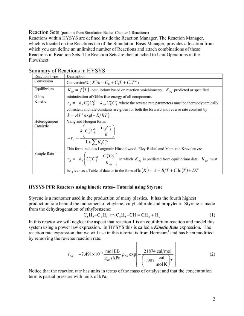
Summary of Reactions in HYSYS
Reaction Type Description:
Conversion Conversion% ( ) 2
210% TCTCCX ++=
Equilibrium ( )TfKeq = ; equilibrium based on reaction stoichiometry. predicted or specified eqK
Gibbs minimization of Gibbs free energy of all components
Kinetic γϕβα
SRrevBAfA CCkCCkr +−= where the reverse rate parameters must be thermodynamically
consistent and rate constants are given for both the forward and reverse rate constant by
( )RTEATk n −= exp
Heterogeneous
Catalytic
Yang and Hougen form:
∑+
−
=−
i
ii
s
S
r
Rb
B
a
A
A CK
K
CCCCk
r γ1
This form includes Langmuir-Hinshelwood, Eley-Rideal and Mars-van Krevelen etc.
Simple Rate
−−=
eq
SR
BAfA K
CCCCkr
γϕ
βα in which is predicted from equilibrium data. must
be given as a Table of data or in the form of
eqK eqK
( ) ( ) DTTCTBAK +++= lnln
HYSYS PFR Reactors using kinetic rates– Tutorial using Styrene
Styrene is a monomer used in the production of many plastics. It has the fourth highest
production rate behind the monomers of ethylene, vinyl chloride and propylene. Styrene is made
from the dehydrogenation of ethylbenzene:
22565256 HCHCHHCHCHC +=−⇔− (1)
In this reactor we will neglect the aspect that reaction 1 is an equilibrium reaction and model this
system using a power law expression. In HYSYS this is called a Kinetic Rate expression. The
reaction rate expression that we will use in this tutorial is from Hermann1 and has been modified
by removing the reverse reaction rate:
−×−= −
T
pr EBEB
K mol
cal1.987
molcal21874exp
kPa sg
EB mol10491.7
cat
2 (2)
Notice that the reaction rate has units in terms of the mass of catalyst and that the concentration
term is partial pressure with units of kPa.
2
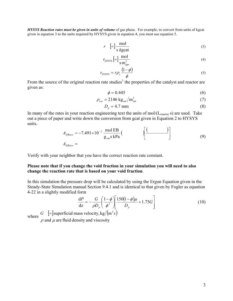
HYSYS Reaction rates must be given in units of volume of gas phase. For example, to convert from units of kgcat
given in equation 3 to the units required by HYSYS given in equation 4, you must use equation 5.
[ ]
gcats
mol
k
r = (3)
[ ] 3
gasms
mol
=HYSYSr (4)
( )
φ
φρ −
=
1
cHYSYS rr (5)
From the source of the original reaction rate studies1 the properties of the catalyst and reactor are
given as:
445.0=φ (6)
3
catcat mkg2146=catρ (7)
mm7.4=pD (8)
In many of the rates in your reaction engineering text the units of mol/(Lreactor s) are used. Take
out a piece of paper and write down the conversion from gcat given in Equation 2 to HYSYS
units.
( ) ( )
=
×−= −
EBnew
EBnew
A
A
kPa sg
EB mol10491.7
cat
2
(9)
Verify with your neighbor that you have the correct reaction rate constant.
Please note that if you change the void fraction in your simulation you will need to also
change the reaction rate that is based on your void fraction.
In this simulation the pressure drop will be calculated by using the Ergun Equation given in the
Steady-State Simulation manual Section 9.4.1 and is identical to that given by Fogler as equation
4-22 in a slightly modified form
( )
+
−
−
−= G
DD
GP
pp
75.111501
dz
d
3
µφ
φ
φ
ρ
(10)
where
[ ] ( )
viscosityanddensity fluid are and
mkg velocity,mass lsuperficia 2
µρ
s=G
3
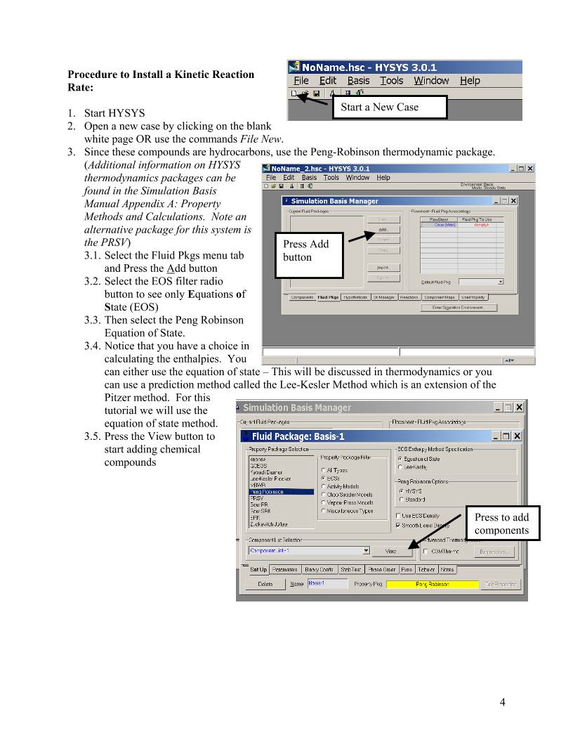
Procedure to Install a Kinetic Reaction
Rate:
Start a New Case 1. Start HYSYS
2. Open a new case by clicking on the blank
white page OR use the commands File New.
Press Add
button
3. Since these compounds are hydrocarbons, use the Peng-Robinson thermodynamic package.
(Additional information on HYSYS
thermodynamics packages can be
found in the Simulation Basis
Manual Appendix A: Property
Methods and Calculations. Note an
alternative package for this system is
the PRSV)
3.1. Select the Fluid Pkgs menu tab
and Press the Add button
3.2. Select the EOS filter radio
button to see only Equations of
State (EOS)
3.3. Then select the Peng Robinson
Equation of State.
tate – This will be discussed in thermodynamics or you
e
3.4. Notice that you have a choice in
calculating the enthalpies. You
can either use the equation of s
can use a prediction method called the Lee-Kesler Method which is an extension of th
Pitzer method. For thi
tutorial we will use th
equation of state method
Press the View button to
start adding chemical
compounds
s
e
.
3.5.
Press to add
components
4
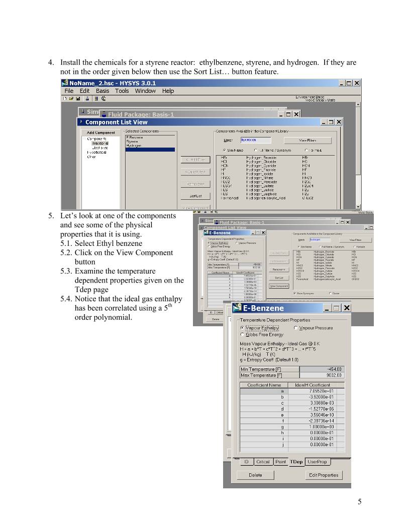
4. Install the chemicals for a styrene reactor: ethylbenzene, styrene, and hydrogen. If they are
not in the order given below then use the Sort List… button feature.
5. Let’s look at one of the components
ponent
5.3. the temperature
on the
5.4. the ideal gas enthalpy
and see some of the physical
properties that it is using.
5.1. Select Ethyl benzene
5.2. Click on the View Com
button
Examine
dependent properties given
Tdep page
Notice that
has been correlated using a 5th
order polynomial.
5
6. Now return to the Simulation Basis Manager by closing the Component List View window.
Press the Close button or X
7. Select the Rxns tab
and then press the
Simulation Basis
Mgr… button. Press here to
start adding
rxns
8. The Reaction
Component Selection
view will appear.
9. Press the Add Rxn
button
10. To install a reaction,
press the Add Rxn
button.
Add
Reaction
11. From the Reactions view, highlight the Kinetic reaction type and
press the Add Reaction button. Refer to Section 5 of the Simulation Basis
Manual for information concerning reaction types and the addition of reactions.
12. On the Stoichiometry tab select the first row of the Component
column in Stoichiometry Info matrix. Select ethylbenzene from
the drop down list in the Edit Bar. The Mole Weight column
should automatically provide the molar weight of ethylbenzene. In
the Stoich Coeff field enter -1 (i.e. 1 moles
of ethylbenzene will be consumed).
6
13. Now define the rest of the Stoichiometry tab
as shown in the adjacent figure.
14. Go to Basis tab and set the Basis as
partial pressure, the base component as
ethylbenzene and have the reaction
take place only in the vapor phase.
15. From your previous hand calculation
given by equation 9 you should have
converted the reaction rate given in
equation 2 by using the following:
( )
kPa sL
mol48.200
L 10
m 1
m 0.445
m
m
m 445.01
m
kg 2146
kg
g10
kPa sgcat
mol10491.7
gas
gas
3
3
gas
3
gas
3
R
3
R
3
cat
3
cat
cat
cat
cat
3
2
=
−
×= −A
(11)
The new reaction rate expression is then given by Equation 12 which should agree with the
calculation:
−−=
T
pr EBEB
K mol
cal1.987
molcal21874
exp
kPa sL
EB mol48.200
gas
(12)
16. The pressure basis units should be kPa and the units of the reaction rate given by equation 12
is mol/(L s). Since the status bar at the bottom of the property view shows Not Ready, then
go to the Parameters tab.
17. Add the pre-exponential which is assumed to give the units given in the basis tab. Then enter
the activation energy – with units of cal/mol (which is transformed to kJ/kmol after entry.)
Leave β blank or place a zero in the cell. Notice that you don’t enter the negative sign with
the pre-exponential.
18. Close the Kinetic Reaction Window
7
Add Set Button 19. By default, the Global Rxn
Set is present within the
Reaction Sets group when
you first display the Reaction
Manager. However, for this
procedure, a new Reaction
Set will be created. Press the
Add Set button. HYSYS
provides the name Set-1 and
opens the Reaction Set
property view.
20. Open the drop down list in
the Edit Bar and select the name of the
Reaction. The Set
Type will correspond to the type of Reaction
which you have added to the Reaction Set.
The status message will now display Ready.
(Refer to Section 5.4 – Reaction Sets for details
concerning Reactions Sets.)
Enter Simulation Environment
21. Press the Close button to return to the
Reaction Manager.
22. To attach the reaction set to the Fluid
thermodynamics), highlight Se
Reaction Sets group and press the Add
to FP button. When a Reaction Set is
attached to a Fluid Package, it become
available to unit operations within the
Flowsheet using that particular Fluid
Package.
Package (your peng robinson
23. The Add ’Set-1’ view appears, from
24. Press the Close button. Notice that the name of the Fluid Package (Basis-
25.
t by
n in
t-1 in the
s
Add to FP (Fluid Package)
which you highlight a Fluid Package
and press the Add Set to Fluid Package
button.
1) appears in the Assoc. Fluid Pkgs group when the Reaction Set is
highlighted in the Reaction Sets group.
Now Enter the
Simulation
Environmen
pressing the butto
the lower right hand
portion
8
PFR
26. Install a PFR reactor. Either through the
26.1. Flowsheet, Add operation
26.2. f12
26.3. or icon pad. Click on PFR, then release left mouse button.
Move cursor to pfd screen and press left mouse button. Double click
on the reactor to open.
27. Add stream names as shown.
28. Next add the reaction set by selecting the reactions tab and choosing Reaction Set from the
drop down menu.
9
29. Go to the Ratings Tab. Remember in the case of distillation columns, in which you had to
specify the number of stages? Similarly with PFR’s you have t specify the volume. In this
case add the volume as 160 m3, 3 m length, and a void fraction of 0.445 as shown in the
figure. Notice that the volume of gas in the reactor or void volume has been calculated.
30. Return to the Reactions tab. Notice that additional data must be entered since you specified a
void fraction. Add the particle size and density of catalyst from equations 7 and 8. Notice
that the bulk density of the catalyst is calculated for you. This has units mass of catalyst per
volume of reactor.
10
Comp
Molar
Flow
Add
Button
Give it a new
name such as
Compositions
31. Go to the Design Tab and select heat
transfer. To make this reactor
adiabatic you need to set the heat
duty to zero. For this tutorial we
will have an isothermal reactor so
leave this unspecified. The yellow
note at the bottom is a warning and
is letting you know that the pressure
drop has not been specified. We will
add this later.
32. Close the PFR Reactor
33. Open the workbook
Workbook
34. Isn’t it strange that you can’t see the molar flowrate in the composition window? Let’s add
the molar flowrates to the workbook windows. Go to Workbook setup.
35. Press the Add button on the right side
36. Select Component Molar Flow and then press the All radio button.
37. To change the units of the variables go
to Tools, preferences
38. Then either bring in a previously
named preference set or go to the
variables tab and clone the SI set and
give this new set a name.
39. Change the component molar flowrate
units from kmol/hr to gmol/s.
40. Change the Flow units from kmol/hr
to gmol/s
41. Next change the Energy from kJ/hr
to kJ/s.
42. Save preference set as well as the case.
Remember that you need to open this
preference set every time you use this
case.
11
43. Now add a feed composition of pure ethylbenzene at 217.5 gmol/s, 2610 gmol/s of water,
880 K, and 1.378 bar. Whoops! We forgot to add the water. Water is used in this reaction
to drive the conversion to higher values. You will see the utility of adding water after you
complete the equilibrium tutorial.
43.1. Go back to the fluid Property package by clicking on the Erlenmeyer flask or
selecting Simulation, Enter Basis Environment.
Return to Fluid Property
Package.
43.2. Go and view Component List-1
43.3. Add water and then return to the
simulation environment by pressing on
the green arrow.
43.4. It will put you in “holding mode”
which stops all calculations. If you
answer yes, then press the Green light
to return to the automatic calculation
mode. Be careful that you have added
water to the correct list. You should be
able to see water in the workbook
component list.
44. Next set the outlet reactor temperature to
880K and the outlet reactor pressure to
1.378 bar to obtain an isothermal and
isobaric reactor. Remember you can type
the variable and then press the space bar and
type or select the units.
Return to
simulation
12
Polymath Solution to Isothermal & Isobaric Reactor
POLYMATH Results
Styrene irreversible rate - volume reactor 2003 02-20-2003, Rev5.1.230
Calculated values of the DEQ variables
Variable initial value minimal value maximal value final value
VR 0 0 160 160
FEB 217.5 18.779137 217.5 18.779137
FS 0 0 198.72086 198.72086
FH 0 0 198.72086 198.72086
FW 2610 2610 2610 2610
P 137.8 137.8 137.8 137.8
rho_cat 2146 2146 2146 2146
T 880 880 880 880
FT 2827.5 2827.5 3026.2209 3026.2209
pEB 10.6 0.8551144 10.6 0.8551144
void_frac 0.445 0.445 0.445 0.445
k 0.3292753 0.3292753 0.3292753 0.3292753
rEB -3.4903181 -3.4903181 -0.281568 -0.281568
XEB 0 0 0.9136591 0.9136591
ODE Report (RKF45)
Differential equations as entered by the user
[1] d(FEB)/d(VR) = rEB
[2] d(FS)/d(VR) = -rEB
[3] d(FH)/d(VR) = -rEB
Explicit equations as entered by the user
[1] FW = 2610
[2] P = 137.8
[3] rho_cat = 2146
[4] T = 880
[5] FT = FEB+FS+FH+FW
[6] pEB = FEB/FT*P
[7] void_frac = 0.445
[8] k = 7.491e-2*rho_cat*(1-void_frac)*exp(-21874/1.987/T)*1000
[9] rEB = -k*pEB
[10] XEB = (217.5-FEB)/217.5
Comments
[1] d(FEB)/d(VR) = rEB
V in L of reactor and P in kPa
[6] k = 7.491e-2*rho_cat*(1-void_frac)*exp(-21874/1.987/T)*1000
mol/(s kPa m^3 reactor)
[9] P = 137.8
kPa
Independent variable
variable name : VR
initial value : 0
final value : 160
Precision
Step size guess. h = 0.000001
Truncation error tolerance. eps = 0.000001
15
46. Comparision to POLYMATH Solution:
46.1. Actual Conversion from HYSYS is 90.09% whereas the POLYMATH solution
gives 91.36%.
46.2. Compare the reaction rates from the hand calculation to that in HYSYS. HYSYS
does not give the initial reaction rate. Instead it gives the reaction rate at the first
iteration of Length. With the default conditions this is at 0.075 m in length. The last
line of the hand calculations given on the previous page was adjusted using the
ethylbenzene molar flowrate at 0.075 m of 192.922 mol/s and the total flowrate at 2852
mol/s. These results are found in the performance tab. The hand calculation gives
6.895×10⁻³ mol/(Lgas s) compared to 6.904×10⁻³ mol/(Lgas s) given by HYSYS below.
16
47. Plots can be obtained from
the Performance tab by
pressing the Plot button.
And selecting the
components that you would
like to plot.
48. To improve the
performance of HYSYS
you need to increase the
number of steps used to
solve the differential
equations. Increase the
number of steps to 40
segments. This results in
an actual conversion of
90.74% compared to 91.36% from POLYMATH. Believe it or not POLYMATH is a more
powerful ordinary differential equation solver than the default used by HYSYS. Increasing
to 200 segments gives a HYSYS conversion of 91.28%. If your simulation is very complex
this number of segments could slow the computer down considerably. You should always
examine reactor behavior at low segment values and then increase the number to check your
solution.
17
49. Now let’s add the pressure drop equation.
49.1. Change the number of segments back to 20.
49.2. Delete the outlet reactor pressure in the worksheet or workbook
49.3. Next go to the Parameters portion of the Design window. Click on the radio
button next to the pressure drop calculation by the Ergun equation. Voila!
50. The rule of thumb for reactors is that the inlet pressure drop should be less than 10% of the
inlet pressure. If the pressure drop is higher than this value then you should do something to
decrease the pressure drop.
01.0 PP ≤∆ (13)
Write the ways that you can decrease the pressure drop given by equation 10:
50.1._______________________________________________________________________
50.2._______________________________________________________________________
50.3._______________________________________________________________________
18
The answers are: G, Dp and z or reactor length.
Making the reactor shorter will decrease the pressure drop.
Decreasing the superficial mass velocity, G, will decrease the pressure drop, but if you
have a production rate that is based on your reactant flowrate how do you decrease G?.
Remember that
cA
00G
ρυ
=
kPa8.13=
. If you have found a volume of reactor that gives a desired
conversion then you need to increase Ac and decrease L (length of reactor) such that the
volume remains constant V HYSYS does this automatically! Try this. The
inlet pressure in 137.8 kPa. A 10% loss in pressure would give an outlet pressure of
124.02 or a . If you get tired of switching back and forth then you could try the
adjust function.
LAc=
∆P
Adjust
51. Add the adjust function. (F4 or Flowsheet palette).
51.1. Select the adjusted variable of reactor tube length and the target variable (the
variable you would like to find) product pressure.
51.2. Go to the Parameters page and change the step size to 0.2 m and set the minimum
to 0.5 m and the maximum to 3 m. Why did you pick these values? You know that 3 m
is gives too large a pressure drop! If you give a really large value of reactor length
HYSYS will yell at you and do strange things! To fix this turn the adjust off by clicking
the ignored box on the connections page. Then go back to the PFR reator and reset the
value of the reactor tube length. Then find out what you did wrong!
51.3. Now you may need to increase your volume to obtain the 90% conversion.
19
52. Changing the particle diameter Dp
is dangerous (well you just need to
be careful)!
If you change the particle size then you
will also change the void fraction of
catalyst. Figure 5-70 of the 5th Edition
of the Chemical Engineers Handbook
shows the relation between particle
diameter and void fraction for various
types of particles.
In Figure 1 shown below is the curve
that I have digitized for spherical
particles. The x-axis is the ratio of the
particle size to the tube or reactor
diameter. This equation can be entered
into a HYSYS spreadsheet so that the
void fraction is automatically calculated
when the particle diameter or reactor
diameter change. Notice that you must
also include the void fraction in your
reaction rate term!
Figure 5-70 in Perry's 5th y = 0.4208x + 0.329
R2 = 0.9989
0
0.1
0.2
0.3
0.4
0.5
0.6
0 0.2 0.4 0.6
Dp/Dtube
vo
id
fr
ac
tio
n
void
Linear (void)
Figure 1: Void Fraction for Spherical Particles
20
POLYMATH and Hand Calculations
53. Now we will look at verifying what is going on in HYSYS. Notice that HYSYS is a black
box calculation. You can’t see what it is doing. Reading the help files will give an
indication on how it is integrating the reactor. To fully understand the PFR let’s go to some
hand calculations given on the following page.
53.1. For the comparison with POLYMATH reset the size of the reactor to the
following a volume of 163 m3 and a length of 2.190 m. You could also add a
spreadsheet for ease in examining variables. Remember that to quickly add variables
you can right click on the variable that you want and drag it to the spreadsheet.
21
Construct a POLYMATH program to give the following:
POLYMATH Results
Pressure Drop in Isothermal Styrene Reactor
Calculated values of the DEQ variables
Variable initial value minimal value maximal value final value
W 0 0 1.941E+08 1.941E+08
FEB 217.5 20.299645 217.5 20.299645
FS 0 0 197.20036 197.20036
FH 0 0 197.20036 197.20036
P 1.378E+05 1.236E+05 1.378E+05 1.236E+05
FW 2610 2610 2610 2610
T 880 880 880 880
k 2.765E-07 2.765E-07 2.765E-07 2.765E-07
FT 2827.5 2827.5 3024.7004 3024.7004
P0 1.378E+05 1.378E+05 1.378E+05 1.378E+05
pEB 10.6 0.8291809 10.6 0.8291809
rEB -2.931E-06 -2.931E-06 -2.292E-07 -2.292E-07
FT0 2827.5 2827.5 2827.5 2827.5
Betacat 6.639E-05 6.639E-05 6.639E-05 6.639E-05
X 0 0 0.9066683 0.9066683
ODE Report (RKF45)
Differential equations as entered by the user
[1] d(FEB)/d(W) = rEB
[2] d(FS)/d(W) = -rEB
[3] d(FH)/d(W) = -rEB
[4] d(P)/d(W) = -Betacat*P0/P*FT/FT0
Explicit equations as entered by the user
[1] FW = 2610
[2] T = 880
[3] k = 7.491e-2*exp(-21874/1.987/T)
[4] FT = FEB+FS+FH+FW
[5] P0 = 1.378e5
[6] pEB = FEB/FT*P/1000
[7] rEB = -k*pEB
[8] FT0 = 217.5+2610
[9] Betacat = 6.639E-05
[10] X = (217.5-FEB)/217.5
Comments
[6] k = 7.491e-2*exp(-21874/1.987/T)
mol/(gcat s kPa)
[8] pEB = FEB/FT*P/1000
kPa
[13] Betacat = 6.639E-05
Pa/g
Independent variable
variable name : W
initial value : 0
final value : 194137890
Precision
Step size guess. h = 0.000001
Truncation error tolerance. eps = 0.000001
25
54. Now let’s compare the solution of POLYMATH with that given in HYSYS.
Volume 163 m3
Catalyst Weight 1.941E+08 kg
Length 2.19 m
HYSYS HYSYS HYSYS HYSYS HYSYS POLYMATH
Number of
Segments
20 200 300 400 500
∆P/P0 (%) 10.01 10.06 10.06 10.07 10.07 10.30
Conversion (%) 89.36 90.58 90.63 90.657 90.66 90.66
Ethylbenzene
Product Flow
(mol/s)
23.15 20.48 20.38 20.33 20.30 20.30
The above values show that HYSYS is using the same equations as those that you entered in
POLYMATH. The 2 differences are in the calculation of pressure drop and the manner in which
the ordinary differential equations are integrated. The difference of 2% in the percent pressure
drop is attributed to the value of viscosity that was used. I assumed that the gases were all steam
with a viscosity of 2.969e-5 kg/(m s). HYSYS uses a value of 2.63E-05 kg/(m s). Plugging the
HYSYS value of viscosity into a spreadsheet to eliminate any round-off errors in the hand
calculation and then placing the new pressure drop value of Betacat = 6.4428E-05 results in a
pressure drop ratio to inlet pressure of 10.01! The method of integration of ODE’s requires an
adjustment of the number of segments to between 400 and 500 to have an precision equal to that
of POLYMATH. We will find in later calculations that a setting of number of segments this
high will cause the HYSYS program to solve very slowly. .
26
At the end of this exercise submit 4 printouts (5 pages total).
1) From a word document printout the following (2 pages): (Paste all of your results into one
word document.) Make the following plots from your Conversion reactor simulation:
a) The effect of reactor length on pressure drop for a constant volume of 163 m3. Notice
that diameter will vary. You may have already done this above by trial and error for a
fixed amount of catalyst to determine the pressure drop at 10% of the inlet pressure.
Before you begin find the limits on the pressure drop – Find out when HYSYS says that
the pressure drop is too big!
b) The effect of reactor diameter on pressure drop for a constant volume of 160 m3. Notice
that length will vary.
c) The effect of changing the particle diameter from 1.2 mm to 0.2 m (really big particles!)
on the pressure drop given that the void fraction from Figure 5-70 in Perry’s 5th edition
for spherical particles is
0.329 0.4208
spherical
+=
tube
p
D
D
φ (14)
Notice that that the void fraction will be nearly constant for this problem and it will be much
less than 0.445! This means that this catalyst was not spherical! To solve this problem just
change the void fraction to the new value. If you needed to change the void fraction as a
function of particle diameter then you would need to do the following:
i) Create a spreadsheet that you can import the particle diameter and the tube diameter.
Then calculate the void fraction and export it to the reactor.
ii) Now you must adjust the reaction rate pre-exponential!
iii) Again make a calculation in the spreadsheet based on equation 5 and then export it
the pre-exponential within the reactor.
iv) To find the pre-exponential term you need to go to the reactor, select the reactions
menu, and view the reaction. See figures on this page for help.
2) On a separate sheet printout the Reaction Summary Printout (See Below for instructions)
3) On a separate sheet printout the Reactor Summary Printout
27
Reaction Summary
1. Go back to the simulation Basis Manager by
clicking on the Erlenmeyer flask.
2. View the reaction
3. Remove the pushpin
4. Select File Print and use the preview feature to
see the following:
5. Print
Reactor Summary:
Double click on reactor
Undo pushpin
Select Print from main menu
Then select the Datablock(s) shown in the
Select Datablock(s) to Print for PFR figure:
Workbook
Select workbook and print.
28
Solutions:
29
Figure 2: Effect of Particle Diameter on Pressure Drop for a reactor with spherical particles and a void fraction of
0.33, volume of 163 m3, length of 2.19 m, diameter 9.73 m and pre-exponential in the rate expression of
107.8 mol/(Lgas s kPa).
Reference:
1 Hermann, Ch.; Quicker, P.; Dittmeyer, R., “Mathematical simulation of catalytic dehydrogenation of ethylbenzene
to styrene in a composite palladium membrane reactor.” J. Membr. Sci. (1997), 136(1-2), 161-172.
30
 WMS仓库系统