tlp250.pdf
- 文件大小: 150.23KB
- 文件类型: pdf
- 上传日期: 2025-08-23
- 下载次数: 0
概要信息:
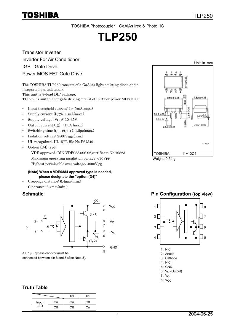
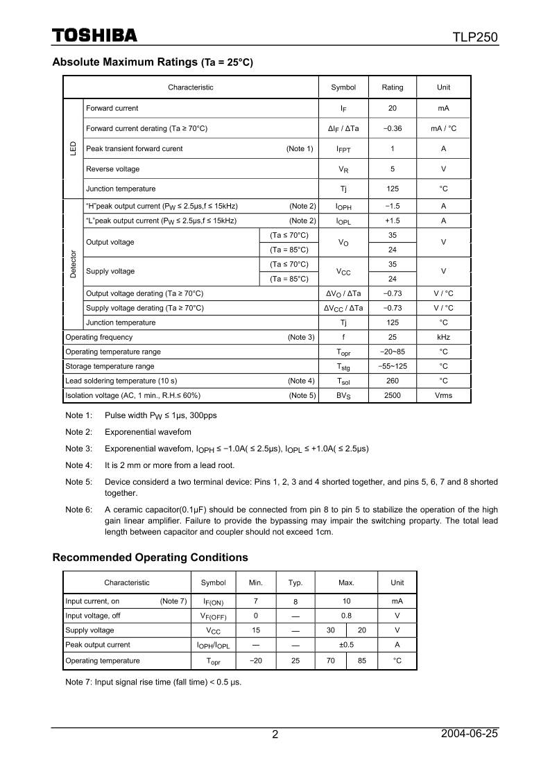
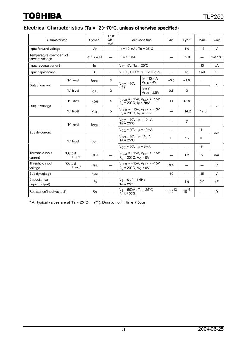
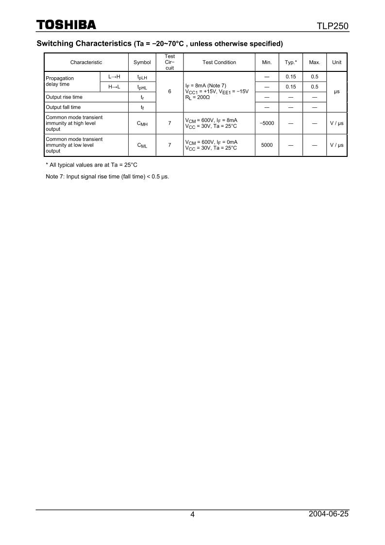
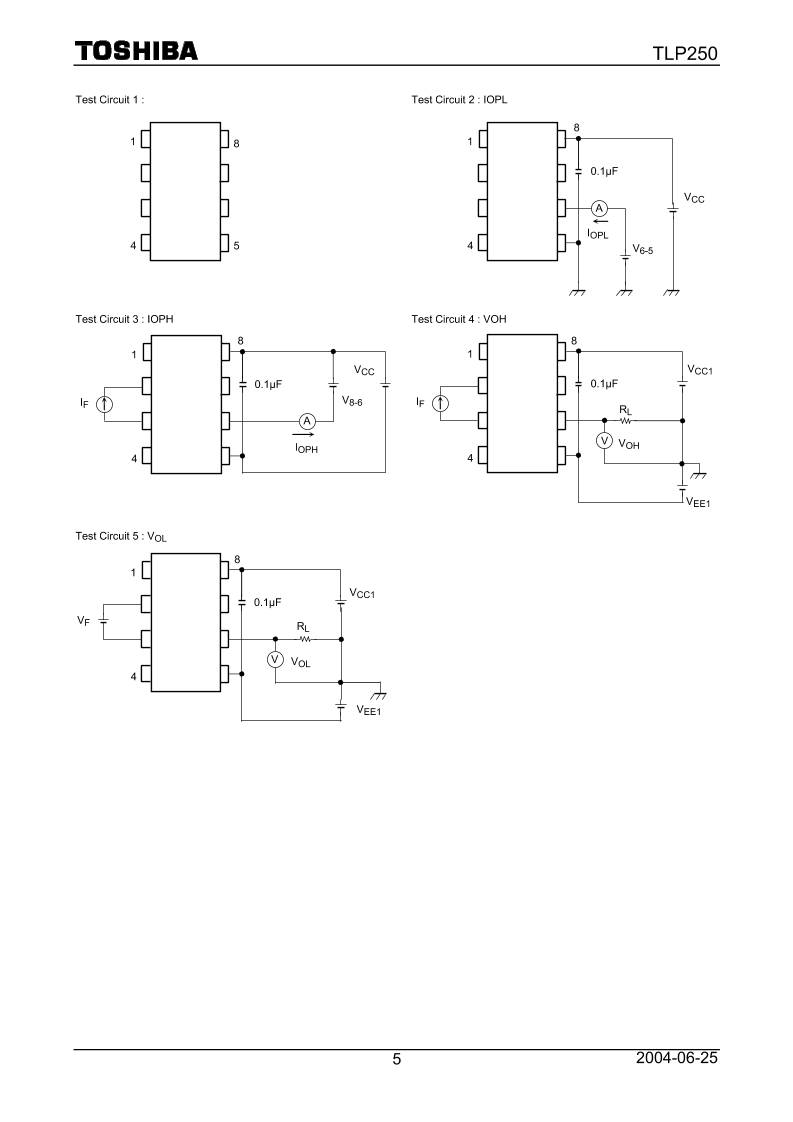
TLP250 2004-06-25 1 TOSHIBA Photocoupler GaAlAs Ired & Photo−IC TLP250 Transistor Inverter Inverter For Air Conditionor IGBT Gate Drive Power MOS FET Gate Drive The TOSHIBA TLP250 consists of a GaAlAs light emitting diode and a integrated photodetector. This unit is 8−lead DIP package. TLP250 is suitable for gate driving circuit of IGBT or power MOS FET. • Input threshold current: IF=5mA(max.) • Supply current (ICC): 11mA(max.) • Supply voltage (VCC): 10−35V • Output current (IO): ±1.5A (max.) • Switching time (tpLH/tpHL): 1.5µs(max.) • Isolation voltage: 2500Vrms(min.) • UL recognized: UL1577, file No.E67349 • Option (D4) type VDE approved: DIN VDE0884/06.92,certificate No.76823 Maximum operating insulation voltage: 630VPK Highest permissible over voltage: 4000VPK (Note) When a VDE0884 approved type is needed, please designate the "option (D4)" • Creepage distance: 6.4mm(min.) Clearance: 6.4mm(min.) Schmatic Pin Configuration (top view) 8 7 6 5 1 : N.C. 2 : Anode 3 : Cathode 4 : N.C. 5 : GND 6 : VO (Output) 7 : VO 8 : VCC 1 2 3 4 2+ VF IF 3- ICC (Tr 1) VO GND (Tr 2) IO VO VCC 8 7 6 5A 0.1µF bypass capcitor must be connected between pin 8 and 5 (See Note 5). Truth Table Tr1 Tr2 On On Off Input LED Off Off On Unit in mm TOSHIBA 11−10C4 Weight: 0.54 g TLP250 2004-06-25 2 Absolute Maximum Ratings (Ta = 25°C) Characteristic Symbol Rating Unit Forward current IF 20 mA Forward current derating (Ta ≥ 70°C) ∆IF / ∆Ta −0.36 mA / °C Peak transient forward curent (Note 1) IFPT 1 A Reverse voltage VR 5 V LE D Junction temperature Tj 125 °C “H”peak output current (PW ≤ 2.5µs,f ≤ 15kHz) (Note 2) IOPH −1.5 A “L”peak output current (PW ≤ 2.5µs,f ≤ 15kHz) (Note 2) IOPL +1.5 A (Ta ≤ 70°C) 35 Output voltage (Ta = 85°C) VO 24 V (Ta ≤ 70°C) 35 Supply voltage (Ta = 85°C) VCC 24 V Output voltage derating (Ta ≥ 70°C) ∆VO / ∆Ta −0.73 V / °C Supply voltage derating (Ta ≥ 70°C) ∆VCC / ∆Ta −0.73 V / °C D et ec to r Junction temperature Tj 125 °C Operating frequency (Note 3) f 25 kHz Operating temperature range Topr −20~85 °C Storage temperature range Tstg −55~125 °C Lead soldering temperature (10 s) (Note 4) Tsol 260 °C Isolation voltage (AC, 1 min., R.H.≤ 60%) (Note 5) BVS 2500 Vrms Note 1: Pulse width PW ≤ 1µs, 300pps Note 2: Exporenential wavefom Note 3: Exporenential wavefom, IOPH ≤ −1.0A( ≤ 2.5µs), IOPL ≤ +1.0A( ≤ 2.5µs) Note 4: It is 2 mm or more from a lead root. Note 5: Device considerd a two terminal device: Pins 1, 2, 3 and 4 shorted together, and pins 5, 6, 7 and 8 shorted together. Note 6: A ceramic capacitor(0.1µF) should be connected from pin 8 to pin 5 to stabilize the operation of the high gain linear amplifier. Failure to provide the bypassing may impair the switching proparty. The total lead length between capacitor and coupler should not exceed 1cm. Recommended Operating Conditions Characteristic Symbol Min. Typ. Max. Unit Input current, on (Note 7) IF(ON) 7 8 10 mA Input voltage, off VF(OFF) 0 ― 0.8 V Supply voltage VCC 15 ― 30 20 V Peak output current IOPH/IOPL ― ― ±0.5 A Operating temperature Topr −20 25 70 85 °C Note 7: Input signal rise time (fall time) < 0.5 µs. TLP250 2004-06-25 3 Electrical Characteristics (Ta = −20~70°C, unless otherwise specified) Characteristic Symbol Test Cir− cuit Test Condition Min. Typ.* Max. Unit Input forward voltage VF ― IF = 10 mA , Ta = 25°C 1.6 1.8 V Temperature coefficient of forward voltage ∆VF / ∆Ta ― IF = 10 mA ― −2.0 ― mV / °C Input reverse current IR ― VR = 5V, Ta = 25°C ― 10 µA Input capacitance CT ― V = 0 , f = 1MHz , Ta = 25°C ― 45 250 pF “H” level IOPH 3 IF = 10 mA V8−6 = 4V −0.5 −1.5 ― Output current “L” level IOPL 2 VCC = 30V (*1) IF = 0 V6−5 = 2.5V 0.5 2 ― A “H” level VOH 4 VCC1 = +15V, VEE1 = −15V RL = 200Ω, IF = 5mA 11 12.8 ― Output voltage “L” level VOL 5 VCC1 = +15V, VEE1 = −15V RL = 200Ω, VF = 0.8V ― −14.2 −12.5 V VCC = 30V, IF = 10mA Ta = 25°C ― 7 ― “H” level ICCH ― VCC = 30V, IF = 10mA ― ― 11 VCC = 30V, IF = 0mA Ta = 25°C 7.5 Supply current “L” level ICCL ― VCC = 30V, IF = 0mA ― ― 11 mA Threshold input current “Output L→H” IFLH ― VCC1 = +15V, VEE1 = −15V RL = 200Ω, VO > 0V ― 1.2 5 mA Threshold input voltage “Output H→L” IFHL ― VCC1 = +15V, VEE1 = −15V RL = 200Ω, VO < 0V 0.8 ― ― V Supply voltage VCC ― 10 ― 35 V Capacitance (input−output) CS ― VS = 0 , f = 1MHz Ta = 25℃ ― 1.0 2.0 pF Resistance(input−output) RS ― VS = 500V , Ta = 25°C R.H.≤ 60% 1×10¹² 1014 ― Ω * All typical values are at Ta = 25°C (*1): Duration of IO time ≤ 50µs TLP250 2004-06-25 4 Switching Characteristics (Ta = −20~70°C , unless otherwise specified) Characteristic Symbol Test Cir− cuit Test Condition Min. Typ.* Max. Unit L→H tpLH ― 0.15 0.5 Propagation delay time H→L tpHL ― 0.15 0.5 Output rise time tr ― ― ― Output fall time tf 6 IF = 8mA (Note 7) VCC1 = +15V, VEE1 = −15V RL = 200Ω ― ― ― µs Common mode transient immunity at high level output CMH 7 VCM = 600V, IF = 8mA VCC = 30V, Ta = 25°C −5000 ― ― V / µs Common mode transient immunity at low level output CML 7 VCM = 600V, IF = 0mA VCC = 30V, Ta = 25°C 5000 ― ― V / µs * All typical values are at Ta = 25°C Note 7: Input signal rise time (fall time) < 0.5 µs. TLP250 2004-06-25 5 Test Circuit 1 : Test Circuit 2 : IOPL Test Circuit 3 : IOPH Test Circuit 4 : VOH Test Circuit 5 : VOL 8 1 4 VCC 0.1µF IOPL A V6-5 8 1 4 VCC1 0.1µF VOL VF RL VEE1 V 5 1 4 8 8 1 4 VCC 0.1µF IOPH V8-6 IF 8 1 4 VCC1 0.1µF VOH V IF RL VEE1 A TLP250 2004-06-25 6 Test Circuit 6: tpLH, tpHL, tr tf Test Circuit 7: CMH, CML CML(CMH) is the maximum rate of rise (fall) of the common mode voltage that can be sustained with the output voltage in the low (high) state. VEE1 VCC1 VO RL 0.1µF 8 IF 100Ω IF VO VOH GND VOL 80% 80% tpLH tpHL tr tf VCM 90% VO 600V CMH CHL 10% tr tf 26V 3V SW :A(IF=8mA) SW :B(IF=0) 0.1µF 8 VCC VO 1 4 VCM + - A B SW IF CML = CMH = 480 (V) tr (µs) tf (µs) 480 (V) TLP250 2004-06-25 7 IF – VF Forward voltage VF (V) Fo rw ar d cu rr en t I F ( m A ) 100 1.0 50 30 10 5 3 1 0.5 0.3 0.1 0.05 0.03 0.01 1.2 1.4 1.6 1.8 2.0 Ta = 25 °C IF – Ta Ambient temperature Ta (°C) A llo w ab le fo rw ar d cu rre nt I F (m A ) 40 0 0 100 20 40 60 80 10 20 30 VCC – Ta Ambient temperature Ta (°C) A llo w ab le s up pl y vo lta ge V C C (V ) 40 0 0 100 20 40 60 80 10 20 30 IOPH, IOPL – Ta Ambient Temperature Ta (°C) A llo w ab le p ea k ou tp ut c ur re nt I O P H , I O P L ( A ) 0 0 100 20 40 60 80 1 2 PW ≦ 2.5 µs, f ≦ 15 KHz ΔVF / ΔTa – IF Forward current IF (mA) Fo rw ar d vo lta ge te m pe ra tu re co ef fic ie nt Δ V F / Δ Ta (m V / °C ) -1.4 0.1 0.3 0.5 1 3 5 10 30 -1.6 -1.8 -2.0 -2.2 -2.4 -2.6 TLP250 2004-06-25 8 • The information contained herein is subject to change without notice. • The information contained herein is presented only as a guide for the applications of our products. No responsibility is assumed by TOSHIBA for any infringements of patents or other rights of the third parties which may result from its use. No license is granted by implication or otherwise under any patent or patent rights of TOSHIBA or others. • TOSHIBA is continually working to improve the quality and reliability of its products. Nevertheless, semiconductor devices in general can malfunction or fail due to their inherent electrical sensitivity and vulnerability to physical stress. It is the responsibility of the buyer, when utilizing TOSHIBA products, to comply with the standards of safety in making a safe design for the entire system, and to avoid situations in which a malfunction or failure of such TOSHIBA products could cause loss of human life, bodily injury or damage to property. In developing your designs, please ensure that TOSHIBA products are used within specified operating ranges as set forth in the most recent TOSHIBA products specifications. Also, please keep in mind the precautions and conditions set forth in the “Handling Guide for Semiconductor Devices,” or “TOSHIBA Semiconductor Reliability Handbook” etc.. • The TOSHIBA products listed in this document are intended for usage in general electronics applications (computer, personal equipment, office equipment, measuring equipment, industrial robotics, domestic appliances, etc.). These TOSHIBA products are neither intended nor warranted for usage in equipment that requires extraordinarily high quality and/or reliability or a malfunction or failure of which may cause loss of human life or bodily injury (“Unintended Usage”). Unintended Usage include atomic energy control instruments, airplane or spaceship instruments, transportation instruments, traffic signal instruments, combustion control instruments, medical instruments, all types of safety devices, etc.. Unintended Usage of TOSHIBA products listed in this document shall be made at the customer’s own risk. • The products described in this document are subject to the foreign exchange and foreign trade laws. • TOSHIBA products should not be embedded to the downstream products which are prohibited to be produced and sold, under any law and regulations. • GaAs(Gallium Arsenide) is used in this product. The dust or vapor is harmful to the human body. Do not break, cut, crush or dissolve chemically. RESTRICTIONS ON PRODUCT USE
缩略图:
高速下载:
正在进行安全检测...
点击后进入安全下载页,再进行实际下载。下载链接有效期 24 小时,过期会自动刷新。
下载说明:
- 文件描述:tlp250.pdf,可用于在线分享与下载使用。
- 文件分类:文档资料
- 用途建议:适用于资料分享、学习交流、办公协作。
- 适合人群:学生、教师、办公人员、项目协作团队。
- 适配系统:Windows、macOS、Android、iOS 均可下载访问。